I have now had the wonderful MiniFactory 3D printer for about three months. As I have little teaching with contact lessons, and hence no need to go to the University every day, I haven’t been able to print something all the time. Nevertheless, I have become somewhat proficient in managing the printer, so I thought I would write a little blog post to illustrate some of the stuff I have picked up along the way.
MiniFactory is located in Seinäjoki, Finland, and its manager Janne Pihlajamäki has been instrumental in getting our machine to work properly. I have contacted him on email and phone, and he has never failed to provide an answer to my questions. He probably thinks me a very nontechnical person, what with the million questions I have sent him, but on the other hand, he’s been getting the word back from the trenches. I hope this is a mutually beneficial set-up. MiniFactory is a startup company, and hence, they have been too busy in building the production line and the machines themselves to get all of the documentation in place yet, but they are doing an admirable job at this difficult business.
The MiniFactory works straight out the box, after you have calibrated it the first time. Calibration gives you a nice, technical, space cadet feeling, because it is done by issuing one command, and then manually guiding the print nozzle to the surface of the table. The command is
G1 X75 Y75 Z-0.1 F900
and after that the nozzle hovers above the table, smack in the center of it. Then you use the Repetier Host manual controls to guide the nozzle so that a sheet of paper is kept stuck under it, but not too stuck. Then you enter the command M114, and note a number on the response the host sends. This number is then entered into the EEPROM configurator by adding it to the current figure, if it is negative, and deducting it, if it is positive.
See the quaint source for error there? I did. Only after I read the manual well enough, though.
What happens if you do not calibrate well, and the nozzle is high? The next picture shows exactly that.

As you can see, the filament has not stuck to the one extruded just before. This is because the filament is extruded in air and then settles down to the tavle, instead of being extruded directly onto the table. These print runs have no chance off survival and must be killed soon to stop wasting filament.
If the print nozzle is too tight, you will not see a print either, because the aperture in the nozzle is closed by the contact with the table glass. Remember, this thing is extruding at 0.3 mm with a layer height of 0.1 mm. So when the nozzle is directly on the table, you hear a screeching noise and the nozzle draws a line in the hairspray that covers the table. Not very productive either.
Assuming the calibration is okay, there is the next thing you need to check. It is actually quite easy to have the table slightly tilted, either along the X axis or the Y axis. This will result in a print that is perfect if your object is very close to the center of the table and does not extend much in any direction, But if you have a print that is on the whole table, you get this:

The table is tilted along the X axis. You can see that the prints in the back are again not properly formed and the filament is extruded in the air, whereas the ones close to the front have been scraped by the print nozzle, and the filament forms clumps (not to mention the blackening the print head causes at 245 degrees C). To fix this, you must first place the heater element again so that it is tight in its slots, and then realign the glass plate so that it is absolutely level.
The next thing I learned the hard way was that you cannot move the table too fast. In Repetier, you can set a bunch of parameters that are related to the printer’s mechanicals, and in Slic3r [sic] you can set parameters related to the operation of the G-code. One of these is the Travel speed:

At some time I read it on a website that you can use a travel speed of 120 millimeters per second. Well, you can. However, the printer will not be able to follow that speed, and it will lose its calibration in the X or Y directions, with this result:

The table moved at the high speed, but the calibration on the Y axis failed, and the printer thought it was in the proper place when it started to extrude the 8th layer. Not really, and this was again a reason to kill the print. The fix to this is to go back to the 60 mm/s speed for travel. In the speed settings window you can see that for perimeters (outer edge of print) is 60 mm/s, but the inner bits (fills) can only be done at 20 mm/s.
The next problem I found was changing the aluminum tube leading to the extruder nozzle. I was sent a new one by the manufacturer, and they asked me to change a working part for a new one. The change itself was not terribly hard, just unscrew the tube and put the other one in. But it happened to have a sharp edge after the tooling, so it started shaving off chips of the ABS filament. These chips appeared everywhere, first they filled the print head casing and then overflowed to the table.
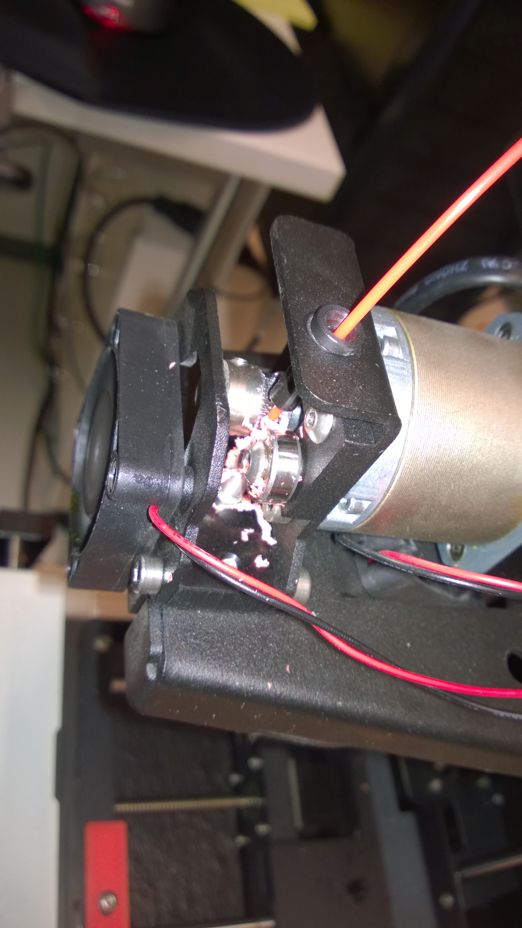
And not just that then, but the chips remained in the tube, and gradually built up a plug. This stopped the flow of the filament, and the print head began to do a virtual 3D print in thin air. Not very productive again, and a reason to kill the process.

You can see the interrupted print on the keyboard – this is a box for an Arduino robot. It has printed the perimeter, and the first solid layer of the box bottom up to a point. Then the chips blocked the tube, and the print was rendered invalid. If you get to the machine just when this happens, you can pause, retract the wire, blow on the print head, reinsert the wire, and extrude until flow is good again, but the chipping will happen again.
The fix was removing the tube again, and then using a Phillips screwdriver to enlarge the opening at the top of the aluminum tube. This got rid of the sharp remnant of the tooling phase, and nowthe filament flows down the tube smoothly. No chipping, no problem. The next image shows the tube, and the second source for filament feed problems.

The feed tube is the straight aluminum bit below the two feed rollers. The rollers are attached to an L-shaped piece of iron that you can move left and right, and this adjusts the tension on the tube. Make it too tight, and the toothed feed roller will chip the line again, make it too lax, and the lack of friction will stop the feeding. I found this out the hard way after I had inserted the newly-screwdrivered feed tube, I didn’t check the tension. And yes, another print failed because of that.
BUT NOW IT WORKS.

This is an image of the machine printing out four identical copies of the ever-present Blender keychain. Now that the calibration is correct, the table is level, speeds are right, and there’s no chipping anymore, the machine can do this endlessly, and issue four keychains in two hours.
![]()
0 thoughts on “Things I have learned of MiniFactory”